HOMER Pro 3.16

A Pumped Hydro System builds potential energy by storing water in a reservoir at a certain height when there is excess energy. It converts the potential energy to electricity by releasing the potential energy to turn the turbine generator when there is a demand. The reservoir is located at a certain height above the turbine generator (the head height) to generate potential energy. The flow rate is the amount of water (meters cubed per second) that flows in or out. You can use the following equation to calculate the energy storage capacity of a pumped hydro system:
E [J] = 9.81ƿwaterVreshheadƞ
Where:
E is the energy stored in joules. Divide by 3.6 x 10⁶ to convert to kWh.
ƿwater is the density of water, usually about 1000 kg/m3.
Vres is the volume of the reservoir in cubic meters.
hhead is the head height in meters.
ƞ is the efficiency of the energy conversion, and must consider losses like turbine efficiency, generator efficiency, and hydrodynamic losses.
You can convert from flow rate in meters cubed per second to power in kW using the following equation:
P [kW] = 9.81 ƿwaterhhead ƞ F / 1000
Where:
F is the flow rate in cubic meters per second.
The storage system in this example is based on the Idealized Storage Model. For many pumped hydro systems, the Idealized Storage Model is the most applicable in HOMER. To learn more about this model, including how to create your own, see the Idealized Storage Model section of the help.
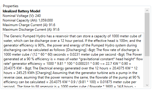
Properties of the Pumped Hydro Storage
The following image and table contain information about the nominal voltage, nominal capacity, and maximum charge and discharge current of the idealized storage. See the Properties area for the Pumped Hydro Storage you selected in HOMER for a complete description.
Variable |
Pumped Hydro Storage System Interpretation |
Nominal Voltage |
The nominal voltage of the generator used in the pumped hydro system. |
Nominal Capacity |
The total potential energy capacity of the reservoir: E [kWh] = 1000 [kg/m^3] * Volume [m^3] * 9.81 [m/s^2] * Head Height [m] / 3.6 x 10^6 [J / kWh]. |
Maximum Charge Current |
Maximum current for charging the reservoir. This can also be computed as maximum pumping power divided by nominal voltage. |
Maximum Discharge Current |
Maximum current produced by discharging the reservoir, or maximum generating power output divided by the nominal voltage. |
Roundtrip Efficiency |
The fraction on energy charging input that is recovered when discharging. This can include electrical losses, hydrodynamic losses, frictional losses, and other sources of loss, if applicable. You can also calculate it as pumping efficiency times generating efficiency, where both numbers are a fraction less than one; i.e., 0.8 * 0.85. |
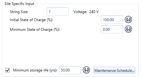
Site-specific Inputs of the Pumped Hydro storage
When using the Idealized Energy Storage model to model the Pumped Hydro Storage component, the site specific inputs are as described in the Idealized Energy Storage section of the help. The Initial State of Charge sets the fraction of the storage reservoir that is filled with water at the start of the simulation. The Minimum State of Charge sets the point when the storage is considered empty and no more energy can be taken out. For Pumped Hydro, this can be set to zero.